#image_title
Ever wondered how to check a diode with a multimeter? Diodes are key in electronics, protecting and switching signals. This guide will show you how to test diodes using a multimeter. You’ll learn to use both Diode Test mode and Resistance mode.
Diodes are key two-terminal devices that let electricity flow in one direction. They have an anode (positive side) and a cathode (negative side). Knowing about them is key for fixing electronic issues. Diodes often fail first, so understanding them is crucial.
A diode lets current flow in one direction but blocks it in the other. This makes them vital in circuits, especially for changing AC to DC. Knowing how they work helps you find circuit problems.
There are many types of diodes, each with its own role in circuits. Here are a few:
Knowing how these diodes work helps you predict their role in circuits. They’re essential for many functions like power conversion, voltage control, and lighting. This knowledge improves your skills in testing and understanding diodes.
Before you start testing diodes, make sure your digital multimeter is set up right. First, turn off all power in the circuit and discharge any capacitors. This step is key to get accurate readings.
Then, choose the right mode on your multimeter. If it has a Diode Test mode, use it. This mode sends a small current to test the diode’s performance. If not, the Resistance mode works too. It measures the diode’s resistance in both directions.
Getting your multimeter ready is the first step in fixing electronic circuits. By setting it up correctly, you ensure your measurements are accurate. Remember, good preparation is essential for effective troubleshooting and keeping your circuits working well.
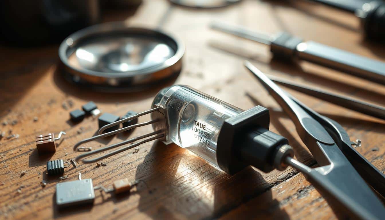
Before you test a diode, it’s important to know which terminals are which. Knowing the anode and cathode helps you test right and avoid mistakes.
Looking closely at electronic parts is crucial for finding diode terminals. A white band on the diode body usually means the cathode. The side without a mark is the anode. For Zener diodes, a black mark shows the cathode.
Diode markings are key to identifying terminals correctly. Knowing these markings helps you set up tests right. This ensures you get accurate results and avoid mistakes.
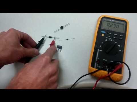
To check diodes with a digital multimeter, start by setting it to Diode Test or Resistance mode. This diode test procedure helps you measure the right values to see if the diode is working.
When in Diode Test mode, connect the positive lead to the anode and the negative lead to the cathode. A good silicon diode will show a voltage drop of 0.6 to 0.7 volts when forward-biased. When it’s reverse-biased, the multimeter should show “OL” or no reading.
If your multimeter doesn’t have Diode Test mode, use Resistance mode instead. A forward-biased diode will have a resistance of a few hundred to a few thousand ohms. When reverse-biased, it should show infinite resistance or “OL”.
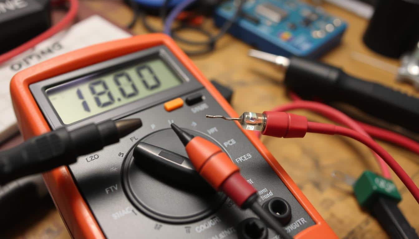
Using a multimeter in Diode Test mode is a top way to check a diode. It lets you see the voltage drop across the diode. This gives you important info about its working state.
Here’s how to do a diode test with a multimeter in Diode Test mode:
Knowing how to read multimeter results is key for checking diodes right:
| Reading | Interpretation |
|---|---|
| 0.6 – 0.7 volts | Healthy silicon diode (forward bias) |
| 0.2 – 0.3 volts | Healthy germanium diode (forward bias) |
| “OL” | Functional diode (reverse bias) |
| Low voltage drop in both biases | Shorted diode |
| “OL” in both biases | Open or non-conductive diode |
This guide will help you do a diode test with a multimeter. You’ll learn to read results for different diodes. This ensures they work well in your circuits.
To do a diode continuity check with a multimeter, first pick the right mode. If your multimeter doesn’t have a Diode Test mode, use the digital multimeter continuity function in Resistance mode. This way, you can check if the diode is working right.
Start by setting your multimeter to Resistance mode. Keep the diode connected to the circuit. Touch the black probe to the cathode and the red probe to the anode. A healthy diode will show a low resistance.
Then, swap the probes. Put the red probe on the cathode and the black probe on the anode. This checks if the diode is working in reverse. A high resistance reading means the diode is not working.
By looking at these resistance values, you can quickly tell if the diode is okay. Here’s a simple guide for using the diode continuity check with the digital multimeter continuity function:
| Reading Condition | Expected Result | Diode Health |
|---|---|---|
| Forward-Biased (Black to Cathode, Red to Anode) | Low Resistance | Good |
| Reverse-Biased (Red to Cathode, Black to Anode) | High Resistance | Good |
| Forward-Biased (Black to Cathode, Red to Anode) | High Resistance | Bad (Open Diode) |
| Reverse-Biased (Red to Cathode, Black to Anode) | Low Resistance | Bad (Shorted Diode) |
If your multimeter doesn’t have a Diode Test mode, you can still test diodes using Resistance mode. This method requires attention but becomes very useful with practice.
Start by setting your multimeter to Resistance mode. To test diodes, connect the positive lead to the anode and the negative lead to the cathode. A good diode will show a resistance of a few hundred ohms to a few kilo-ohms.
If you reverse the leads, the multimeter should show “OL” (overload) or very high resistance. This means the diode is in the reverse-biased state.
This method can be made simpler with a table. It shows the expected readings for both conditions:
| Bias Condition | Expected Reading |
|---|---|
| Forward-Biased | Few hundred ohms to few kilo-ohms |
| Reverse-Biased | “OL” or very high resistance |
By comparing these readings to a known good diode, you can check the health of the diode. This is especially useful when you need to confirm the results from Resistance mode testing. Remember, this method is key to making sure your electronic parts work right.
Testing rectifier diodes is key to making sure AC is safely turned into DC. Knowing how to test these diodes helps spot problems early. This prevents issues with power supplies.
Rectifier diodes are vital for changing AC to DC. If they fail, power supplies don’t work well or stop working altogether. Testing them regularly keeps systems running smoothly.
To start testing rectifier diodes with a multimeter, follow these steps:
Remember these important precautions when testing rectifier diodes:
When checking semiconductor diodes with a multimeter in a circuit, it’s key to isolate the diode first. This prevents interference from other parts. Here’s a simple guide for in-circuit diode testing.
After testing, put the diode’s lead back on the circuit board. These steps help do in-circuit diode testing accurately without harming other parts. Always follow these steps to keep your electronic circuits working well.
| Steps | Description |
|---|---|
| 1. Isolation | Lift one end of the diode from the circuit board. |
| 2. Multimeter Setup | Switch to Diode Test or Resistance mode. |
| 3. Probe Connection | Attach probes with correct polarity to the diode. |
| 4. Reading Observation | Check for voltage drop in forward bias and high resistance in reverse bias. |
| 5. Reconnection | Reconnect the diode back to the circuit board. |
When you use a multimeter to check diodes, knowing about common problems is key. These include open and shorted diodes. Understanding and fixing these issues helps keep your electronics working right.
Open diodes block current flow, showing “OL” on your multimeter. On the other hand, shorted diodes let current flow in both directions. They might show a small voltage drop or low resistance.
To fix diode issues, use both Diode Test and Resistance modes on your multimeter. The Diode Test shows the diode’s forward voltage drop directly. Resistance mode helps by measuring resistance. These methods are crucial for identifying diode problems and keeping electronics running smoothly.
Understanding the unique properties of LED diode testing and the Zener diode test procedure is key. Both diodes work differently, needing specific tests to check their performance.
To test LED diodes, first find the anode (positive lead) and cathode (negative lead). Use your multimeter’s Diode Test mode. Connect the probes as shown. The LED should light up in forward bias, showing it works. But, it should not light up in reverse bias.
Zener diode testing is more complex. You need a circuit to measure the voltage across the Zener diode when it’s reverse biased. The voltage should match the Zener voltage listed for that diode. If it does, the diode is working right.
It’s crucial to know the special traits of LEDs and Zener diodes for testing. This ensures you get accurate results and they work well.
By sticking to these steps, you can quickly check your specialty diodes and see if they’re working.
| LED Diode Testing | Zener Diode Test Procedure |
|---|---|
| Identify anode and cathode | Set up test circuit |
| Use Diode Test mode | Measure voltage under reverse bias |
| Check LED lights in forward bias | Compare with Zener voltage |
| Ensure no light in reverse bias | Confirm operational status |
Learning to test diodes with a multimeter is key for anyone working with electronics. This guide showed you how to test different diodes using a multimeter. It’s important to know how to set up your multimeter and understand the results.
The diode testing summary covers how to tell diodes apart and understand their markings. It also talks about using special tests for LEDs and Zener diodes. Testing diodes in circuits helps find problems quickly and keeps your electronics working well.
It’s crucial to follow safety rules and understand what the results mean. Doing this prevents damage to your tools and parts. This multimeter diagnostics conclusion shows that using a multimeter well helps find and fix diode problems fast. This skill makes you better at fixing electronics.
Unleash your creativity with the EXCEART 1 Set/14pcs Bulb Accessory Kit. Perfect for DIY enthusiasts,…
Read our comprehensive review of the 10ft Pendant Light Cord Socket, an exquisite blend of…
Full review of the Mini Light Bulb Kit SQXBK, a versatile bulb and holder set…
Discover the energy-efficient Super White 6000K DC 12V-20V LED Cluster. Perfect for low voltage, off-grid…
Explore the detailed review of the DIY Antique Brass Lamp Making Kit. Discover its features,…
Delve into the comprehensive review of the YUEONEWIN 500Pcs 5mm LED Diode Kit. Uncover its…