#image_title
Did you recognize that a small component like a diode is crucial to the dependability of your electronic circuit? It is essential to assess diodes properly to prevent issues and ensure that your projects run smoothly. This manual will instruct you how to evaluate a diode effectively. Mastering diode testing can aid you in resolving complications and enhancing your proficiency.
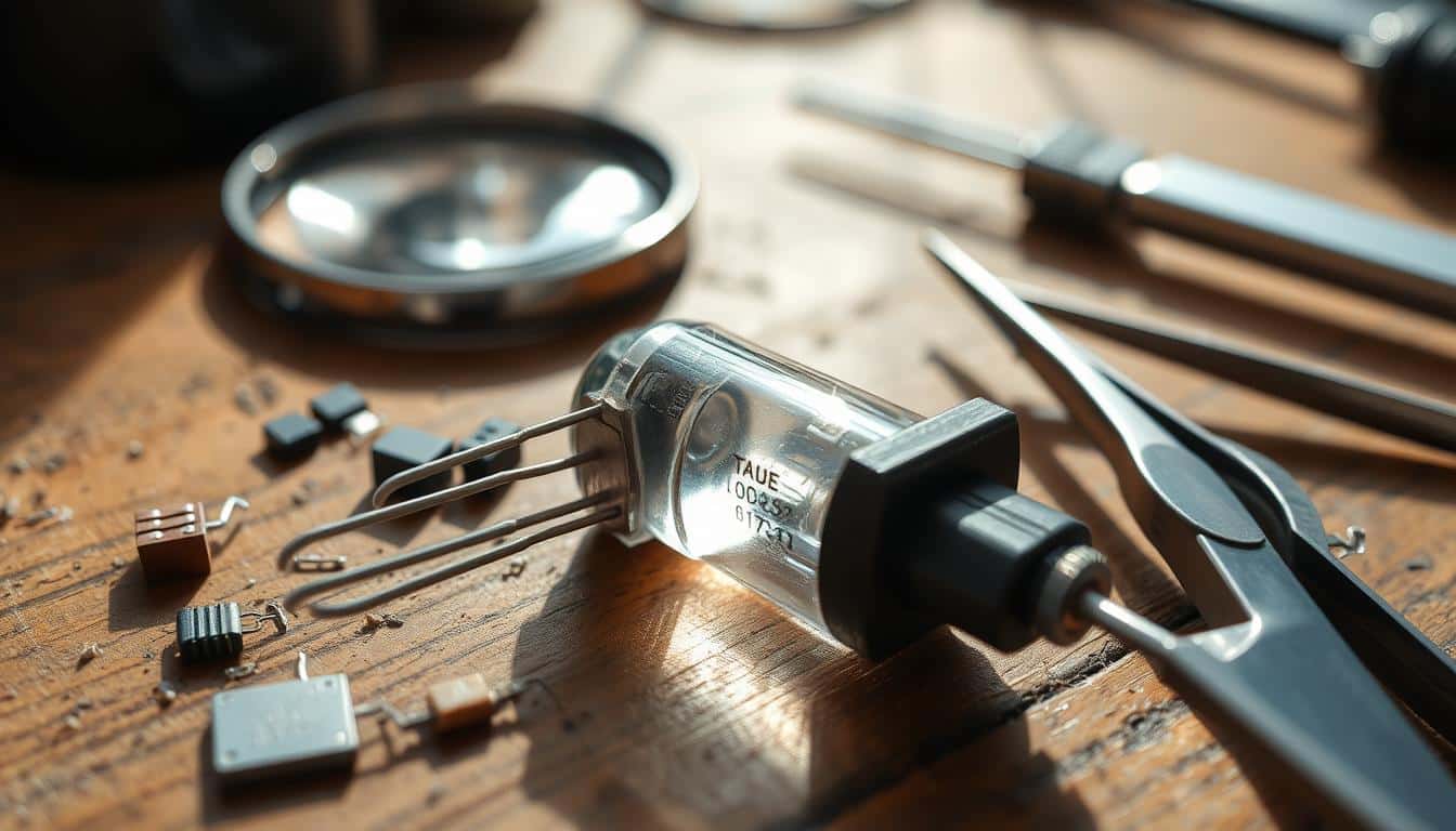
A diode is a two-terminal device constructed from semiconductor material. It allows current to flow in just one direction, making it essential in numerous electronic circuits.
Diodes have various applications, such as in power supply units and signal processing. They are fundamental for these functions.
A diode permits current flow when it is forward-biased and blocks it when it is reverse-biased. A standard Silicon diode requires about 0.7V to begin conducting, which is crucial for verifying if a diode is functioning properly.
Diodes are present in many electronic devices and serve various purposes, including:
Comprehending how diodes function in these capacities enhances your ability to test semiconductors and aids in identifying functional diodes. This guarantees that your electronic projects are more durable and perform better.
When handling diodes, being aware of diode polarity is essential. Diodes permit current to flow in only one direction, making it critical to differentiate the anode from the cathode for accurate testing.
Most diodes feature a clear indication to identify the cathode. A stripe or distinct mark on one end indicates its cathode, while the opposite end represents the anode. Recognizing these terminals is the first step to test diode continuity.
The anode connects to the positive side of the circuit, whereas the cathode connects to the negative side.
The importance of diode polarity in testing cannot be overstated. Reversing connections can result in inaccurate outcomes and potentially damage the diode and instruments. When you test diode continuity, maintaining the correct polarity is crucial for obtaining reliable measurements.
This demonstrates how the diode functions within the circuit, impacting the overall system’s efficiency and reliability.
Verifying a diode’s functionality is vital for maintaining the proper operation of electronic circuits. Testing diodes helps prevent failures and identifies issues early on, ultimately conserving time and resources.
Evaluating diodes is essential to avert circuit failures. A faulty diode can disrupt the entire circuit, leading to significant complications or even total breakdown. Conducting regular assessments and replacing defective components ensures the optimal performance of your devices.
Learning how to diagnose and rectify diode problems is equally important. Understanding how to troubleshoot diode and detect malfunctioning diode issues enables you to identify problems swiftly. This capability enhances your troubleshooting effectiveness and sharpens your diagnostic skills.
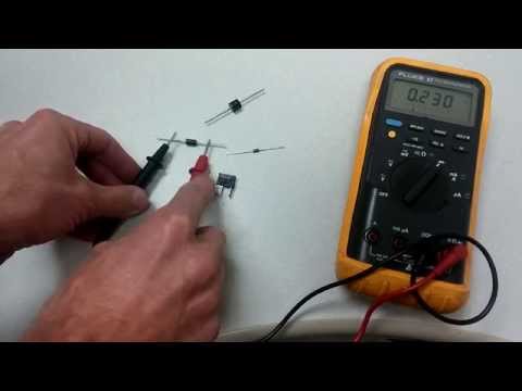
To accurately test diodes, you must have the proper tools. A digital multimeter and a diode identification chart are essential. They facilitate thorough evaluation of the diodes.
A digital multimeter is indispensable for diode testing. It should feature diode and ohmmeter functions. This allows you to check the integrity and polarity of the diode.
Ensure your multimeter is in good working order and calibrated correctly to achieve optimal results.
A diode identification chart is also crucial. It assists you in distinguishing various types of diodes. This ensures you can test each one accurately.
Since diodes vary in configuration and function, the chart simplifies the identification process. Recognizing symbols and numbers allows for quicker testing.
| Tool | Purpose | Key Features |
|---|---|---|
| Digital Multimeter | Diode Testing | Diode and Ohmmeter Functions |
| Diode Identification Chart | Diode Differentiation | Symbols and Numbers |
When you embark on testing electronic components, it is crucial to be well-prepared. This entails organizing your testing area, locating the diode’s terminals, and employing the appropriate tools.
Firstly, obtain a digital multimeter. It is vital for performing accurate diode evaluations. Identify the anode and cathode of the diode; the anode typically has a positive sign or a longer lead. The cathode may have a band or a shorter lead.
Next, set your multimeter to the diode test mode. This mode allows a small current to pass through, enabling you to observe the voltage drop. If your multimeter lacks a diode mode, utilize the ohmmeter mode but understand the distinctions to obtain accurate readings.
Errors in testing can compromise your results or damage the diode. Here are some common pitfalls:
By thoroughly preparing and steering clear of these mistakes, you can master how to evaluate a diode effectively. This leads to trustworthy testing outcomes.
To ensure your diodes function effectively in electronic circuits, it’s important to learn how to test them using a digital multimeter. This guide will outline two main techniques for testing diodes: Diode Mode and Ohmmeter Mode. These methods assist in identifying faults and verifying a diode’s health.
The diode mode on your multimeter provides a straightforward means to assess the diode’s forward bias voltage drop. Here’s what to do:
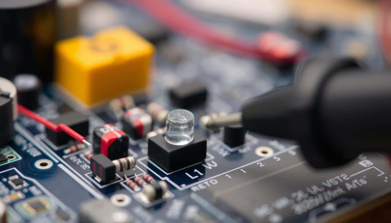
The ohmmeter mode allows you to assess the diode’s resistance in both forward and reverse biases. Here’s how:
in both directions indicates it’s open.
Obtaining precise readings from these evaluations is crucial to determine if your diodes are functioning properly. Regularly testing diodes ensures your electronic circuits operate seamlessly.
Assessing a diode using an analog multimeter involves verifying its resistance in two directions. This technique differs slightly from digital multimeters but is equally effective.
The findings from your analog multimeter are crucial for confirming whether the diode is functioning correctly. Low resistance signifies that the diode allows current to pass. High resistance or an overlimit reading indicates it’s blocking current. This assists you in assessing the diode’s performance within electronic circuits.
To accurately test a diode using an analog meter, it’s essential to comprehend these resistance readings. This knowledge enables you to identify and resolve any problems with the diode.
Diodes may encounter a variety of common issues that could disrupt your circuits. Understanding these problems and how to evaluate them is crucial. This insight will allow you to easily distinguish between functional and faulty diodes.
A major concern arises when diodes are open. An open diode presents high resistance during testing, indicating that current cannot flow through it. This is a clear indication for replacement.
Another prevalent issue involves shorted diodes. A shorted diode exhibits low or zero resistance in both directions, which permits current to flow unimpeded, potentially leading to significant circuit failures.
Leaky diodes present additional concerns, allowing some current to pass in the reverse direction and indicating intermediate resistance. This leakage can decrease circuit efficiency.
| Diode Problem | Indicators |
|---|---|
| Open Diode | High resistance |
| Shorted Diode | Low or zero resistance |
| Leaky Diode | Intermediate resistance |
Grasping the characteristics of healthy diodes and identifying defective ones will enhance your troubleshooting abilities. Effectively utilizing a multimeter will enable you to swiftly identify these common issues, ensuring your circuits function reliably and efficiently.
Assessing an LED involves identifying its terminals and conducting appropriate tests to determine its functionality. It’s essential to recognize which lead is the anode and which is the cathode. This understanding will assist you in addressing any issues with LEDs.
To pinpoint the LED terminals, look for the longer lead, which denotes the anode, while the shorter lead signifies the cathode. Knowing this is critical as the LED must be forward biased for proper testing.
Utilize a digital multimeter set to diode mode. Connect the red probe to the anode and the black probe to the cathode. If the LED illuminates, it indicates that it is functioning and allows current to flow when forward biased.
If the LED does not illuminate, it may require further examination. By adhering to these procedures, you can ensure your LED operates correctly. If issues persist, seek additional methods to ascertain the problem with the diode.
Evaluating a Zener diode involves understanding its unique feature, the Zener breakdown voltage. To accurately *test diode with multimeter* for Zener diodes, follow specific procedures and utilize the appropriate testing circuit.
Zener diodes operate in reverse bias when voltage exceeds a certain threshold, known as the Zener breakdown voltage. This characteristic is essential for maintaining voltage stability. By establishing the correct test conditions, you can determine if the Zener diode is functioning effectively during semiconductor tests.
Once the voltage reaches the Zener breakdown voltage, the diode begins conducting, allowing for accurate measurement of the breakdown voltage. Employ a *multimeter* to check the reading.
Here’s a comprehensive table demonstrating how to *test diode with multimeter* for Zener breakdown voltage:
| Step | Description |
|---|---|
| 1 | Establish the reverse bias circuit with the Zener diode. |
| 2 | Connect a variable power supply to the circuit. |
| 3 | Gradually increase the voltage. |
| 4 | Monitor the multimeter reading to determine the breakdown voltage. |
| 5 | Confirm the Zener breakdown voltage for precision. |
Diode malfunctions can significantly disrupt electronic circuits. It is vital to conduct diode testing accurately to maintain proper functionality. Determining whether diodes are open or shorted is crucial for diagnosing issues. Let’s explore how to efficiently identify and troubleshoot diode problems.
An open diode fails to conduct electricity in either direction during diode testing. To detect an open diode:
Identifying open diodes accurately is essential to resolving troubleshoot diode issues, thereby preventing circuit malfunctions.
Recognizing a shorted diode is critical when you troubleshoot diode issues. This ability helps ensure your electronic devices operate smoothly.
| Issue | Diode Mode Reading | Ohmmeter Mode Reading |
|---|---|---|
| Open Diode | No continuity in either direction | High resistance in both directions |
| Shorted Diode | Continuity in both directions | Low resistance in both directions |
Knowing when to replace a diode is crucial for maintaining the safety and efficiency of your electronic circuits. If you continually receive poor diode readings during evaluations, it may be time for a replacement. Stay vigilant for signs such as unexpected voltage drops or unusual resistance readings.
A healthy diode will show a specific voltage drop during tests. If it fails to do so, displaying an open circuit in both directions, immediate replacement is necessary.
working properly. Conversely, a shorted diode will exhibit extremely low or no resistance in either direction.
To assist you in determining when to replace a diode, refer to this table. It lists common indicators and recommended actions:
| Indicator | Expected Reading | Recommended Action |
|---|---|---|
| Forward Voltage Drop | 0.6V – 0.7V (for silicon diodes) | Normal – No replacement required |
| Open Circuit in Both Directions | Infinite in both directions | Replace the diode |
| Short Circuit in Both Directions | Zero or near-zero in both directions | Replace the diode |
By closely monitoring these signs, you can detect faulty diodes. This ensures your circuit operates efficiently.
Understanding how to test a diode is essential for maintaining the efficacy of your electronic circuits. By acquiring these skills, you facilitate the smooth operation of your systems. This minimizes the risk of breakdowns and conserves resources on repairs.
Whether utilizing a digital or analog multimeter, knowing how to evaluate components is vital. It saves both time and money. We have covered key subjects such as locating the anode and cathode, the significance of diode polarity, and the distinctions in testing LEDs and Zener diodes.
Each section of this manual equips you with the tools to prevent errors and enhance your troubleshooting abilities. This knowledge empowers your devices to function more effectively for extended periods.
By incorporating diode testing into your regular maintenance routine, your circuits will achieve greater reliability. This ensures your electronic components remain efficient and durable.
Unleash your creativity with the EXCEART 1 Set/14pcs Bulb Accessory Kit. Perfect for DIY enthusiasts,…
Read our comprehensive review of the 10ft Pendant Light Cord Socket, an exquisite blend of…
Full review of the Mini Light Bulb Kit SQXBK, a versatile bulb and holder set…
Discover the energy-efficient Super White 6000K DC 12V-20V LED Cluster. Perfect for low voltage, off-grid…
Explore the detailed review of the DIY Antique Brass Lamp Making Kit. Discover its features,…
Delve into the comprehensive review of the YUEONEWIN 500Pcs 5mm LED Diode Kit. Uncover its…