#image_title
Have you ever considered how to assess a diode with a multimeter? It’s essential for repairing electronics correctly. Understanding how to evaluate diodes can signify the difference between a functioning circuit and one that fails.
Diodes play a vital role in electronics, managing current flow. To ensure they operate effectively and prevent damage, it’s crucial to test them properly. This guide will demonstrate how to utilize a multimeter to identify and resolve diode issues, benefitting everyone from enthusiasts to professionals looking to enhance their expertise.
Diodes are fundamental components in electronics that regulate current flow. They function akin to a unidirectional valve for electricity, allowing current to pass in only one direction when correctly configured. This characteristic makes diodes crucial in various electronic devices.
A diode consists of two semiconductor materials, forming a p-n junction. This junction enables the diode to conduct electricity when forward biased while blocking it when reverse biased.
Understanding diode polarity is vital for their proper functioning within circuits. Recognizing which side is the anode and which is the cathode is essential during semiconductor component testing.
Numerous types of diodes exist, each serving its unique purpose:
Diodes find diverse applications, making them highly significant in modern electronics:
Understanding the various types and applications of diodes enhances one’s capability in semiconductor component testing and troubleshooting electronic issues.
Testing diodes is critical for ensuring they function correctly in electronic circuits, allowing current to flow appropriately. Identifying faulty diodes is essential to prevent potential damage to other circuit components.
Diodes are vital for power delivery, voltage management, and safeguarding circuits from voltage surges. Any issues can lead to incorrect voltage readings, circuit failures, or subpar performance. Conducting diode tests maintains circuit integrity and protects electronic components.
Diodes ensure current flows correctly, maintaining circuit efficiency. By verifying diode polarity, you confirm the diode’s proper installation, leading to effective circuit operation.
Locating defective or impaired diodes is a crucial aspect of troubleshooting electronic circuits. A malfunctioning diode can disrupt circuit performance or cause total failure. Testing diodes for defects aids in quickly identifying problems and preventing more significant complications.
Defective diodes can severely impact a circuit if left unaddressed. Regular testing and verifying diode polarity ensure only functional components remain in your circuit, preventing damage and sustaining optimal performance.
Maximizing the utility of an electronic device involves refining its circuit performance. By conducting diode tests, you can ensure all components work cohesively, which is crucial for long-term circuit efficiency and reliability.
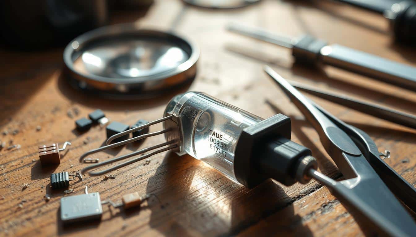
Initiating diode testing necessitates having the appropriate tools and equipment. These instruments assist in obtaining accurate readings and assessing diodes’ functionality.
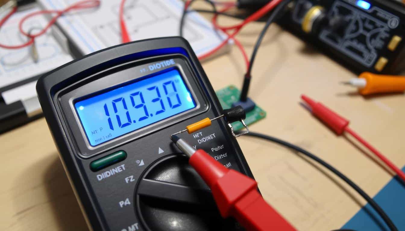
A digital multimeter is essential for diode testing, equipped with specific settings for diode evaluation that deliver accurate measurements.
High-quality test leads are crucial for obtaining precise readings. They connect your multimeter to the diode, so choose sturdy leads for effective testing.
A power source, such as a battery or power supply, is necessary for testing the forward and reverse bias of the diode.
A breadboard simplifies the testing setup, securely holding the diode in place for hands-free testing.
Additional tools like alligator clips and a magnifying glass can be beneficial. They assist in securing the diode and examining it for damage. These tools are vital for comprehensive multimeter diode evaluations.
| Equipment | Description |
|---|---|
| Digital Multimeter | Device featuring multimeter diode test settings critical for precise readings. |
| Test Leads | Connect multimeter to diode, essential for multimeter continuity test. |
| Power Source | Battery or power supply to facilitate testing procedures. |
| Breadboard | Simplifies setup and stabilizes diode. |
Having these tools prepared ensures efficient diode testing, which is crucial for electrical repair and maintenance.
Testing a diode with a multimeter is straightforward once you comprehend the procedure. You should utilize both the Diode Test Mode and Resistance Mode on your digital multimeter.
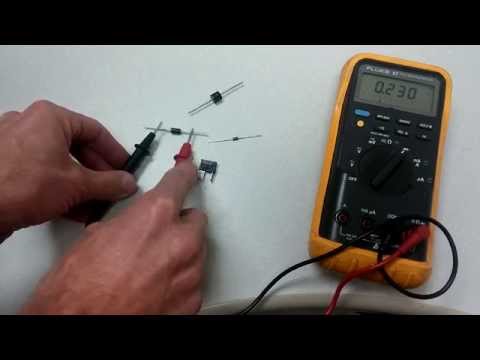
The first task is to determine the anode and cathode of the diode. The anode is typically the longer lead without a marking, while the cathode has a stripe or other indication.
In the Diode Test Mode, you can evaluate the forward bias voltage drop. Attach the red lead to the anode and the black lead to the cathode. A normal silicon diode should display a voltage drop between 0.5 to 0.8 volts.
If your multimeter does not feature a Diode Test Mode, you can utilize the Resistance Mode for a comprehensive evaluation. Set the multimeter to measure resistance. In forward bias, connect the red lead to the anode and the black lead to the cathode. A functioning diode will indicate a resistance between 1000 Ω to 10 MΩ.
In reverse bias, a healthy diode will display ‘OL’ or show no current flow.
The diode test mode on a multimeter is essential for assessing diodes. Follow these guidelines for a proper evaluation.
Initially, ensure that all power is off and capacitors are discharged to prevent incorrect readings or damage. Then, configure your multimeter to the diode test mode.
For forward bias, connect the red lead to the anode and the black lead to the cathode, allowing current to flow. A functional diode will exhibit a voltage…drop of 0.6 to 0.7 volts for silicon, and 0.2 to 0.3 volts for germanium.
In reverse bias, interchange the leads: black to the anode and red to the cathode. A functioning diode displays ‘OL’ (over-limit), indicating no current is flowing.
Comprehending your multimeter measurements is essential. A stable voltage drop in forward bias signifies the diode functions properly. An infinite reading indicates it’s open. In reverse bias, ‘OL’ affirms it’s operational. However, similar low voltage readings could suggest it’s shorted. Accurate evaluation of multimeter diode testing settings is crucial for verifying diode polarity and status, preventing damage.
When assessing diodes in resistance mode, it’s important to configure your multimeter correctly. This guarantees you achieve precise readings. It’s an effective method for identifying and resolving defective diodes. Here’s how to execute it correctly:
To begin, set your multimeter to the resistance mode (Ω). Ensure the diode is removed from any circuit. This allows you to obtain clear readings.
For forward bias resistance:
| Diode Status | Forward Bias (Resistance) | Reverse Bias (Resistance) |
|---|---|---|
| Functional Diode | High | ‘OL’ (Open Loop) |
| Defective Diode (Open) | High | High |
| Defective Diode (Shorted) | Low | Low |
For reverse bias resistance:
Compare your findings with a known operational diode. This helps verify if your test diode is functioning correctly.
Diodes play a crucial role in numerous electronic circuits but may encounter issues. Recognizing these problems is imperative for maintaining circuit functionality.
An open diode fails to permit current to flow in any direction. When examining diodes, an ‘OL’ (over limit) reading on a multimeter indicates it’s defective. This renders the diode ineffective.
A shorted diode behaves like a closed switch. It exhibits a low voltage drop in both directions. If a diode consistently shows a low reading, it’s shorted. This can lead to malfunctions or damage in circuits.
Another concern is an inconsistent voltage drop. If it falls outside the range of 0.5 to 0.8 volts for silicon diodes, it may be faulty. Identifying these issues helps maintain proper circuit function.
| Problem | Indicators | Diagnosis Technique |
|---|---|---|
| Open Diode | No current flow, multimeter shows ‘OL’ | Measure with multimeter in both biasing modes |
| Shorted Diode | Continuous low voltage drop in all directions | Measure voltage drop across the diode |
| Irregular Voltage Drop | Voltage strays from 0.5-0.8V (silicon diodes) | Check voltage drop against standard metrics |
Understanding how to resolve common diode issues is essential. It enhances the reliability and efficiency of electronic circuits.
Evaluating specialized diodes involves checking their polarity and voltage drop. It also ensures each diode operates correctly in its application. Here’s how to test various types of diodes.
LEDs are unique as they illuminate. Ensure you determine polarity accurately by observing the lead lengths. The longer lead is the positive terminal. Utilize your multimeter in Diode Test Mode to check functionality.
Zener diodes require testing when not energized. When evaluating them, ensure the voltage exceeds their breakdown threshold. This indicates when they commence allowing current to flow.
Schottky diodes switch quickly and display low voltage drops. When testing them, verify these characteristics. Employ your multimeter to observe the voltage drop and confirm it’s low. This is essential for their application in rapid operations.
Grasping advanced electronic repair methods is vital. This encompasses precise diode testing strategies. We’ll examine fundamental techniques, such as oscilloscope application, testing high-power diodes, and evaluating temperature coefficients.
Oscilloscope application is crucial in advanced diode evaluation. It allows observation of diode behavior at various frequencies. This instrument is excellent for identifying issues by demonstrating voltage variations over time.
For optimal outcomes, ensure your oscilloscope settings correspond to the diode being tested.
Testing high-power semiconductors is significant for industrial and power-intensive applications. These diodes require specialized equipment to manage high voltages and currents. Thorough testing ensures they function effectively under demanding conditions.
This mitigates the risk of equipment failure and enhances system robustness.
| Criterion | Standard Diodes | High-Power Diodes |
|---|---|---|
| Voltage Capacity | Up to 100V | Exceeding 1000V |
| Current Capacity | Up to 10A | Exceeding 50A |
| Application | Consumer Electronics | Industrial Systems |
Temperature coefficient evaluation is vital for diodes exposed to fluctuating temperatures. It assesses how temperature variations influence diode performance. This is crucial for consistent operation across varying temperatures.
By performing this evaluation, you can prevent complications caused by temperature shifts. This bolsters the reliability of your electronic systems.
Maintaining precise records of diode evaluations is essential for upholding electronic circuit integrity. Comprehensive diode testing records facilitate comparison of diode performance over time. This ensures they consistently meet required specifications.
This practice also aids in identifying trends or patterns promptly. It enables you to take action before issues escalate.
By meticulously documenting these outcomes, you can observe how diodes perform throughout their lifespan. This is critical for targeted maintenance. It enhances the reliability of electronic circuits over time.
| Test Date | Diode Type | Forward Voltage (V) | Reverse Voltage (V) | Comments |
|---|---|---|---|---|
| 2023-10-01 | Standard Diode | 0.7V | 20V | Normal Functioning |
| 2023-10-05 | Zener Diode | 0.7V | 5.6V | Verified for Zener Functionality |
| 2023-10-10 | Schottky Diode | 0.2V | 15V | Normal Functioning |
Maintaining consistent and detailed diode testing records is critical. It supports ongoing initiatives in upholding electronic circuit integrity. It assists in diagnosing problems and monitoring component life span. This is essential for both preventative maintenance and future foresight.
Excelling in diode testing with a multimeter is essential for anyone engaged in electronic repairs. You can identify issues such as open or shorted diodes and voltage drops. This ensures your circuits operate efficiently and your devices remain dependable.
Acquiring knowledge about specialized assessments for LEDs, Zener diodes, and Schottky diodes enhances your expertise. Employing devices like oscilloscopes or evaluating temperature factors deepens your understanding of diodes. This comprehensive strategy bolsters your components’ efficacy and longevity.
Maintaining records of your assessments is equally vital. A comprehensive log facilitates continuous circuit inspections and upkeep. This underscores the significance of precise testing in your daily tasks. Adhering to these guidelines enables you to manage your systems effectively, ensuring they remain dependable and perform optimally.
Unleash your creativity with the EXCEART 1 Set/14pcs Bulb Accessory Kit. Perfect for DIY enthusiasts,…
Read our comprehensive review of the 10ft Pendant Light Cord Socket, an exquisite blend of…
Full review of the Mini Light Bulb Kit SQXBK, a versatile bulb and holder set…
Discover the energy-efficient Super White 6000K DC 12V-20V LED Cluster. Perfect for low voltage, off-grid…
Explore the detailed review of the DIY Antique Brass Lamp Making Kit. Discover its features,…
Delve into the comprehensive review of the YUEONEWIN 500Pcs 5mm LED Diode Kit. Uncover its…